Firmware / Embedded Engineering
In the vast majority of modern products, microprocessors and microcontrollers are essential for delivering the intended functionality. These devices manage complex operations that would be impossible to achieve through conventional hardware alone. Thanks to advances in semiconductor technology, even relatively compact products can now perform sophisticated tasks that were once considered unthinkable.
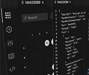
The system’s core behavior is driven by its firmware. This specialized software processes millions of instructions per second to handle varying inputs and environmental conditions.
Firmware development is a vital and highly specialized area within the broader product development process. Embedded engineers are responsible for translating functional requirements into precise software instruction sets that guide the system's behavior.

The Embedded Systems Software Development Lifecycle (SDLC) - also referred to as the Embedded Software Development Process - is a structured framework comprising a series of steps and activities used to design, develop, validate, test, deploy and maintain software embedded within a hardware system.
This lifecycle represents a holistic and disciplined approach to managing embedded product development from initial concept through to full-scale production and field operation. It integrates both engineering principles and project management best practices to ensure reliability, performance, compliance and long-term maintainability.
The SDLC engineering roadmap equips our developers and system designers with the tools, methodologies, and resources needed to efficiently create, upgrade, and support high-quality embedded solutions tailored to client requirements, including lifecycle feedback, version control and continuous improvement processes.
The Embedded Firmware Development Process encompasses a wide range of parameters, extending beyond intended functionality to include environmental, operational, and system-level constraints. The system must therefore be designed as an integrated, all-encompassing solution capable of reliable decision-making and control. The following outlines the development process.
█ Define System Specifications
This phase defines both hardware and software requirements, including system features, functional behavior, performance targets, interfaces and operational constraints required for an effective and robust design.
█ Design Hardware Platform
The hardware platform includes components such as microcontrollers, memory, interfaces and supporting circuitry. It also covers schematic design, PCB layout, and Bill of Materials (BOM), enabling a fully tailored system architecture.
█ Develop Software Platform
The software platform may include operating systems (e.g., Linux or RTOS), middleware, and firmware. Development tools (e.g., CodeFusion Studio™) and, where applicable, external frameworks (e.g., .NET, Android, iOS) are used for system integration, control and user interfacing.
█ Design Product
The final phase defines the complete product implementation, including hardware, mechanical and industrial design. Key documentation includes the Functional Specification Document (FSD), Chip Design Documents (CDD), Environmental Specifications (ESD) and Bill Of Materials (BOM).
A detailed Technical Design Requirement Specification (TDRS) document should be created as part of the product development process. This document serves as a blueprint for the entire product lifecycle and ensures alignment between engineering, manufacturing and business goals.
The specification should include, but not be limited to, the following key elements:
● Purpose of the Product.
● System Block Diagram.
● Main Features and Functions.
● Environmental Conditions.
● Regulatory and Compliance Requirements.
● Mechanical and Industrial Design Constraints.
● Manufacturing and Testing Requirements.
● Interfaces and Connectivity.
● Power Supply Requirements.
● Firmware and Software Requirements.
A well-structured specification document ensures clarity, reduces miscommunication across teams, and sets a solid foundation for development, validation and manufacturing.
Once the Technical Design Requirement Specification (TDRS) is complete, our software development engineers move on to the detailed design phase. At this stage, each block in the system is analyzed to select appropriate components and finalize the application circuits.
Our software developers and engineers make key decisions such as determining the type of power supply to use, whether it should be a linear regulator, a DC-DC switching converter, or another solution. Based on these decisions, the specific power management ICs (PMICs) are selected and their application circuits are carefully designed & validated. This process is repeated for every functional block in the system to ensure optimal performance, reliability and efficiency.
Here is a systematic breakdown of this process:
█ 1. Requirements & System Architecture
● The Embedded Engineers collaborate with System Architects and Hardware Engineers to define software requirements based on the product’s intended functionality.
● They contribute to shaping the system architecture by advising on microcontroller/microprocessor selection, memory requirements, interface compatibility and real-time constraints.
█ 2. Hardware Design Phase
● The Embedded Engineers work closely with the Hardware Design Team.
● They review schematics, assist in component selection (e.g., MCUs, sensors, communication modules) and ensure that the hardware supports the intended software features.
● Initial board bring-up code and bootloader frameworks are also developed during this phase.
█ 3. Software Design & Development
● At this stage in the process the Embedded Engineers operate fully on the software development.
● This includes writing low-level drivers, middleware, application logic, communication stacks, integrating real-time operating systems (RTOS), and implementing power management features.
● Emdedded Engineers involvement in iterative development and testing on evaluation boards.
█ 4. Integration & Testing
● The Embedded Engineers test software on actual hardware (prototypes).
● The engineers perform unit testing, integration testing and hardware-in-the-loop (HIL) testing.
● They identify and resolve issues related to hardware-software interactions through in-depth debugging and analysis.
█ 5. Validation, Certification & Production Support
● The Embedded Engineers help with the System Engineers to validate software against the original TDRS, ensure compliance with standards and prepare production-ready firmware.
● Post-production, the Embedded Engineers support the System Design Engineers with firmware updates, bug fixes and feature enhancements (e.g., OTA updates).
Engineers often observe that products performing flawlessly in controlled laboratory settings, can encounter unexpected issues once deployed in the field. This discrepancy arises because operational environments introduce unpredictable variables that differ vastly from lab conditions. To ensure reliable performance, engineers must anticipate and simulate these diverse environmental and operational factors during validation and testing, well before deployment.
One of the most common challenges arises when maintaining signal integrity in high-speed digital interfaces exposed to real-world electromagnetic conditions. In laboratory environments, signal paths are typically optimized with ideal routing and minimal noise, but once deployed, products may be affected by electromagnetic interference, ground loops, or impedance mismatches. Differential pairs on a PCB, for example, may fail to maintain controlled impedance due to layout constraints in production, resulting in data corruption or intermittent communication failures. To mitigate such issues, engineers often employ robust signal conditioning techniques such as impedance matching, proper line termination, and the use of common-mode chokes or ferrite beads to suppress noise. While simulation and controlled impedance testing are invaluable, field validation remains essential to uncover unforeseen interactions within complex electromagnetic environments.
Wireless connectivity poses a similar set of challenges. Devices relying on LTE-Advanced or 5G technologies can experience fluctuating signal strength and inconsistent throughput depending on local coverage, network congestion, or environmental obstructions. Reproducing such dynamic and variable conditions in a laboratory setting is inherently difficult. For this reason, extensive field testing, often including drive testing and real-world channel characterization, is crucial to accurately evaluate connectivity performance.
Environmental and mechanical factors further complicate product validation. Extreme temperatures, humidity fluctuations, mechanical vibrations, and pressure variations can all significantly impact reliability and functionality. Comprehensive testing under these diverse conditions, frequently guided by standards such as HALT, HASS, or MIL-STD-810, is vital to confirm a product’s long-term durability and operational robustness.
Ultimately, while laboratory testing provides critical insights during development, only extensive field validation can confirm a design’s true resilience against real-world variables. Anticipating and testing for these conditions ensures that products not only meet performance expectations in theory, but also continue to operate reliably throughout their lifecycle in authentic operational environments.
Once field trials have been completed over several weeks or months, the insights and performance data collected become an invaluable source of information for design refinement. Each observation, whether a confirmed failure, a minor anomaly, or a consistent pattern in user feedback, provides engineers with practical evidence of how the product behaves under true operational conditions. This information must be carefully analyzed and translated into concrete design improvements, ensuring that all identified issues are effectively addressed in the next design iteration.
It is equally important that any lessons learned from field testing are used to enhance the validation and production testing processes themselves. Updating test plans, validation procedures, and production screening methods ensures that similar issues are identified much earlier in future development cycles. For instance, if a field trial reveals that certain connectors loosen under prolonged vibration, vibration profiles and mechanical endurance tests in the validation stage should be revised accordingly. This approach prevents recurrence and steadily raises the maturity level of both the product and the production process.
By embedding these findings into a continuous improvement framework, engineers create a feedback loop that strengthens every phase of development, from early prototyping to final mass production. Over time, this iterative process enhances design robustness, manufacturing consistency and overall product reliability. The result is a product that not only performs well in controlled conditions but also maintains that performance consistently across diverse, unpredictable real-world environments, truly ready for the field and for long-term deployment.
Before launching the product, several critical elements beyond the product itself must be prepared to ensure, [1] a smooth market entry and, [2] a smooth user experience. These include:
█ Product Certification
The product must comply with relevant certification standards based on its features and the regions where it will be sold. This could include safety, electromagnetic compatibility (EMC), wireless communication and environmental standards, among others. Each target market (e.g., CE for Europe, FCC for the US, BIS for India etc.) may have different requirements.
█ Product Documentation
Comprehensive and accessible documentation is essential. This should include:
● Detailed product page on the company website.
● Quick introduction or unboxing video.
● Technical datasheet outlining specifications.
● A clear and concise User Manual.
● Setup guides and troubleshooting tips.
● A dedicated support channel or helpdesk for customer assistance.
More Specifics...
Firmware engineering and Embedded high-end audio automation systems go beyond a simple one-page overview. These systems rely on real-time processing, precise control and acoustic tuning to optimize performance. Embedded microcontrollers and DSP chips handle dynamic range compression, noise reduction, multi-channel synchronization. Automation with remote diagnostics and system optimization. For a deeper understanding of the technologies behind our professional audio solutions, feel free to reach out by phone or email.
Measurable operational improvements
An analysis of the project results and underlying KPIs shows that 92% of our projects met their development timelines, an improvement compared to previous years. This indicates that the ongoing adjustments to process optimization and team integration are having a positive impact. We remain focused on further improving our working methods to ensure your product is delivered on schedule.
WITHIN DEADLINE
PROJECT TEAM
ENGINEERING